


Two-Point Perspective.
Takeaways

Good to go
Two-point perspective
Two-point perspective is a drawing system that uses lines, shapes, and scale to create an illusion of three-dimensional depth on a two-dimensional surface by representing forms or spaces as seen from a single point. Dimensions and proportions are established by the Closest Vertical line that runs near the centre of the drawing, while lines receding on both sides converge at two separate vanishing points on the horizon line.
- The Closest Vertical is your measurement foundation
Unlike one-point perspective, two-point perspective uses a single vertical line near the centre of the drawing as the only place where true measurements can be applied. All other dimensions must be calculated using perspective methods, such as diagonal division, as no other surfaces remain parallel to the picture plane. - The horizon line position determines what surfaces you see
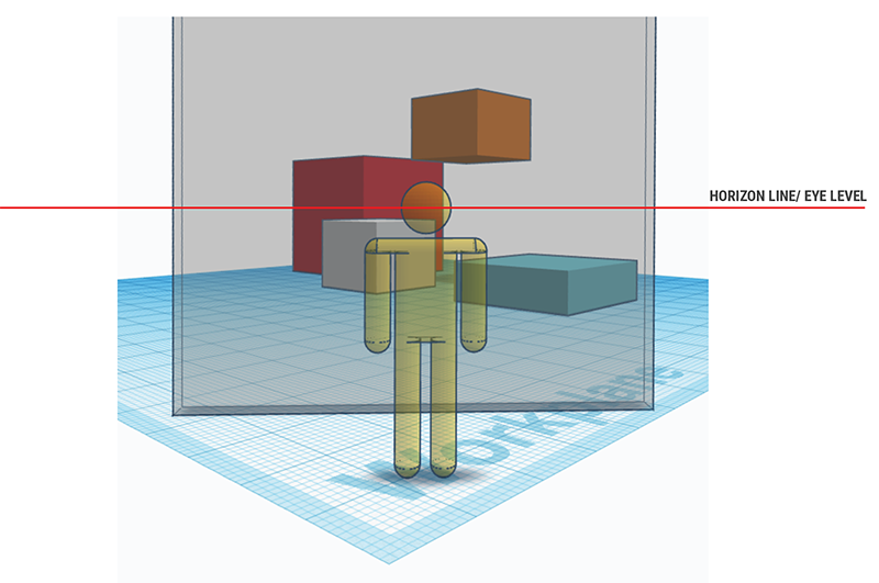
The viewer's eye level controls which faces of objects are visible: when positioned above objects, you see top surfaces; when below, you see bottom surfaces; when at mid-height, you see neither tops nor bottoms. This relationship between eye level and the horizon line is crucial for creating believable spatial relationships. - Proportions change dramatically with rotation
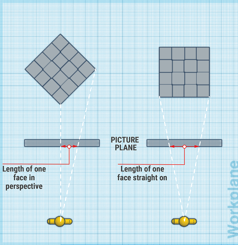
Objects viewed in two-point perspective appear much slimmer on their receding faces compared to their actual dimensions. Students must develop an understanding of these proportional changes rather than relying on mathematical precision, making sides narrower than heights to maintain a realistic appearance. - Finding centres requires diagonal construction methods
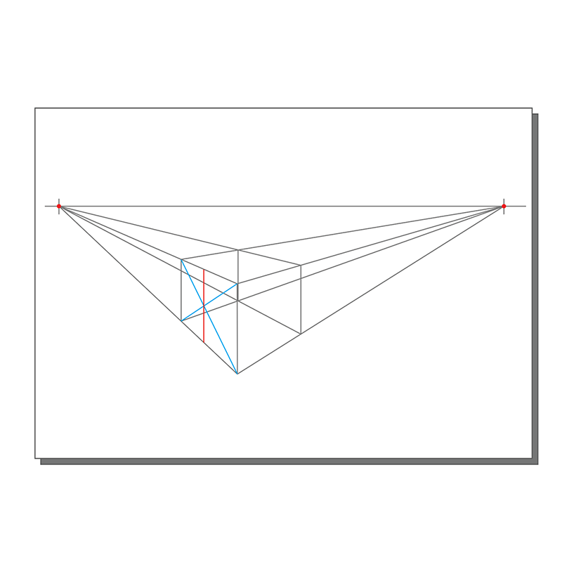
Since rulers cannot measure dimensions on receding planes, centres must be found using diagonal lines that intersect to locate precise midpoints. This technique is essential for creating complex forms, such as pyramids or saw-tooth roofs, and for dividing surfaces into equal sections or grids.
Introduction to Two-point Perspective
Perspective drawing is a system that represents parallel lines as converging as they recede away from a viewer. The components of perspective drawing include a horizon line (or eye level) and vanishing points. Perspective was invented in the 15th Century in Northern Europe.
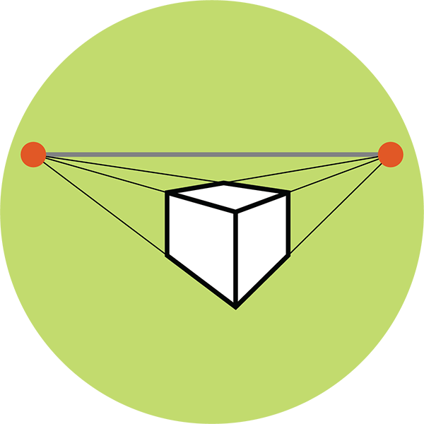
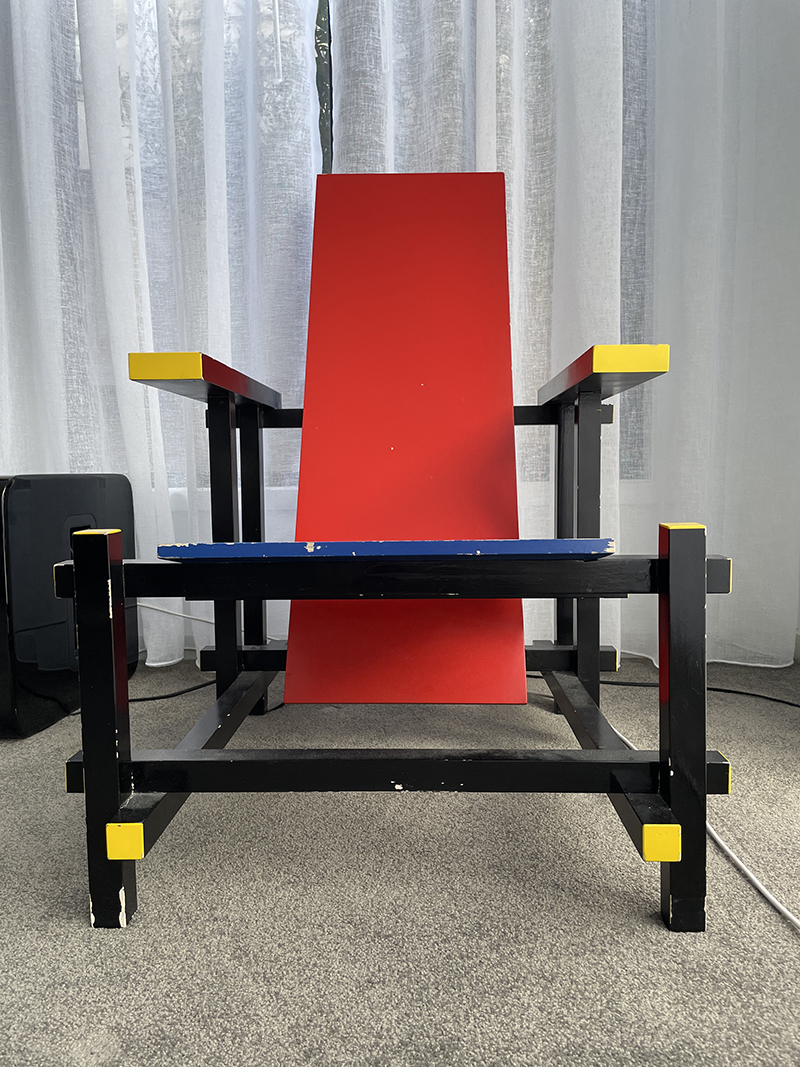
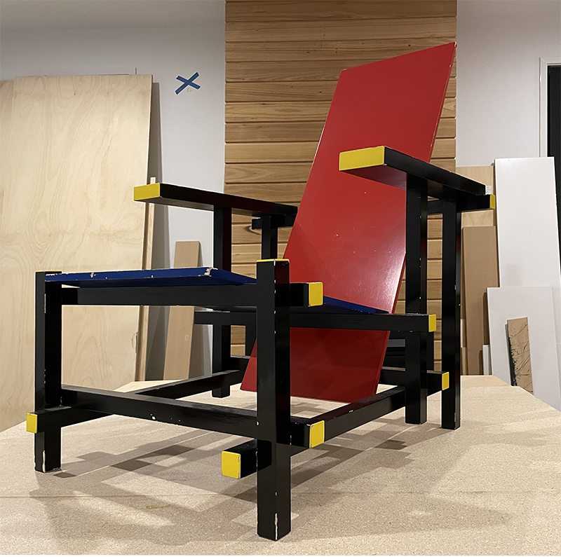
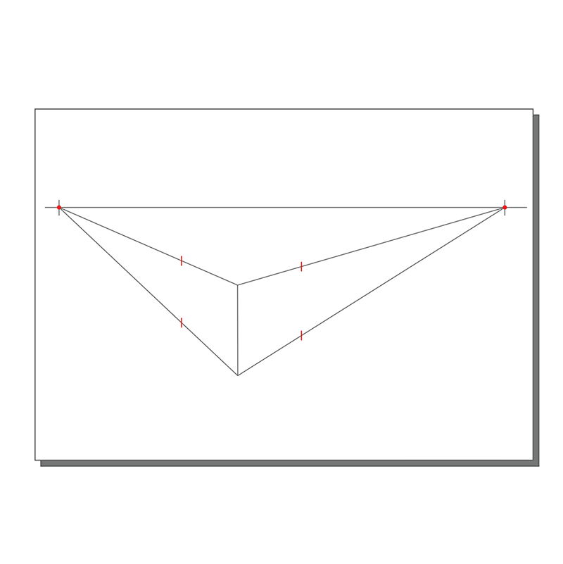
Two-Point perspective represents a form or space as would be observed from one corner. Dimensions and proportions of objects are set by the Closest Vertical line that runs near the centre of the drawing and is parallel with the Picture Plane. Lines receding on both sides of the Closest Vertical converge at two Vanishing Points to the left and right of the object. These Vanishing Points are situated on a Horizon Line. The height of the Horizon Line (also called Eye Level) and the distance between the Vanishing Points are set by the position of the viewer or camera.
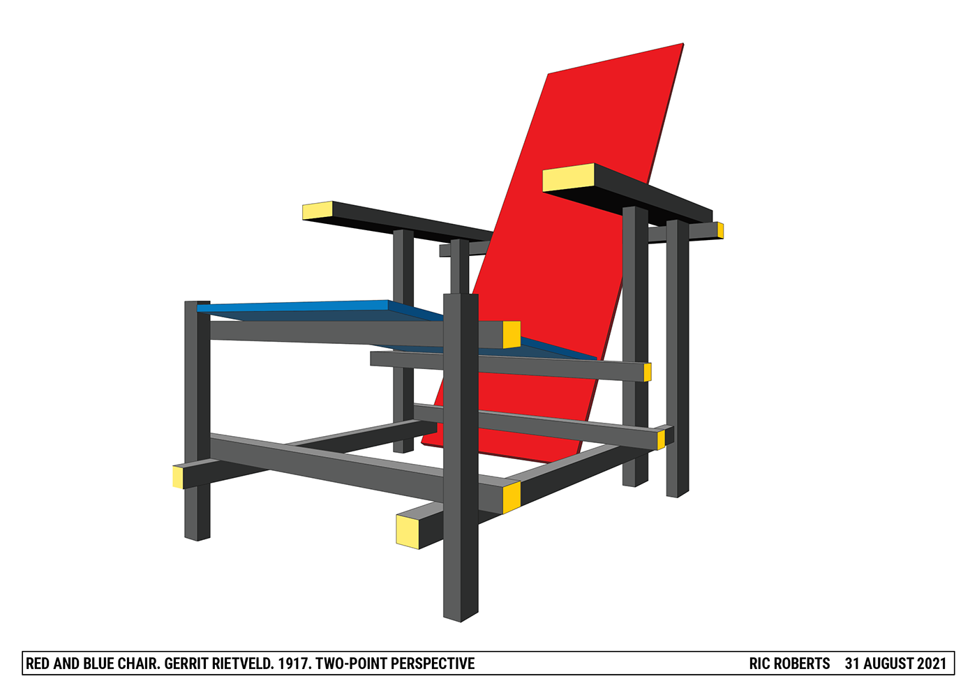
Two-point perspectives are frequently used by environmental and industrial designers to represent buildings and objects.
Model answer
Jump to
History of perspective
Jump to
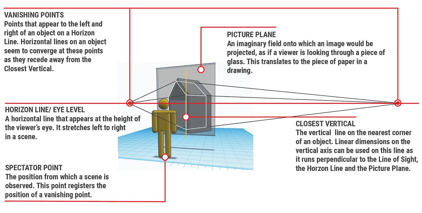
Components of Two-Point Perspective
How it works
Knowing your perspective
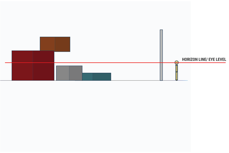
In the task below students are asked to use their camera to visualise objects in One-Point and Two-Point Perspective. This helps to understand the factors that create each kind of Perspective method.
In each case, the Horizon Line has been placed at mid height on the object to avoid a Three-Point Perspective distortion to the vertical lines.
task

1.1 look around
Jump to
Drawing an object in Two-Point Perspective
CAUTION

Process for drawing in One-Point Perspective
Skill 1. Making my first box
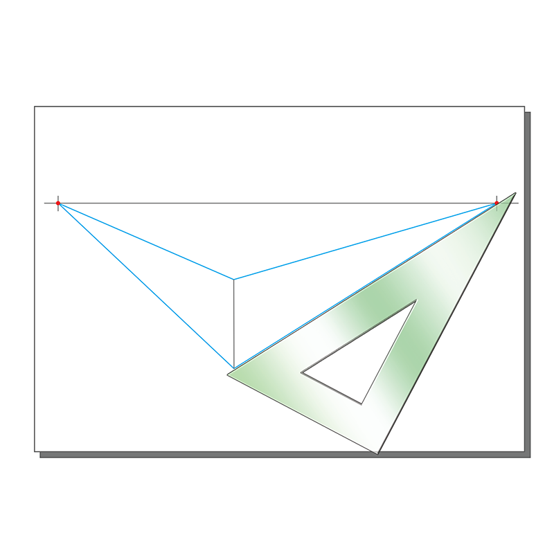
task
2.1 My first box
Jump to
Skill 2. Above and below the horizon line

task
3.1 Floating boxes
3.2 use photography
Jump to
Skill 3. Finding a centre in perspective
The pyramid

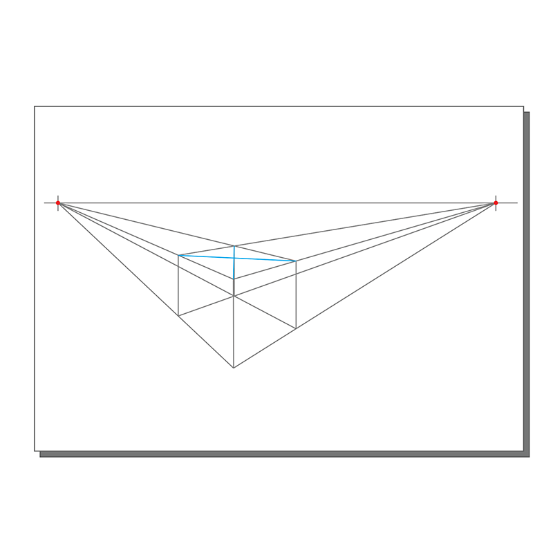

The saw-tooth


task
4.1 finding centres
Jump to
Proportions in perspective
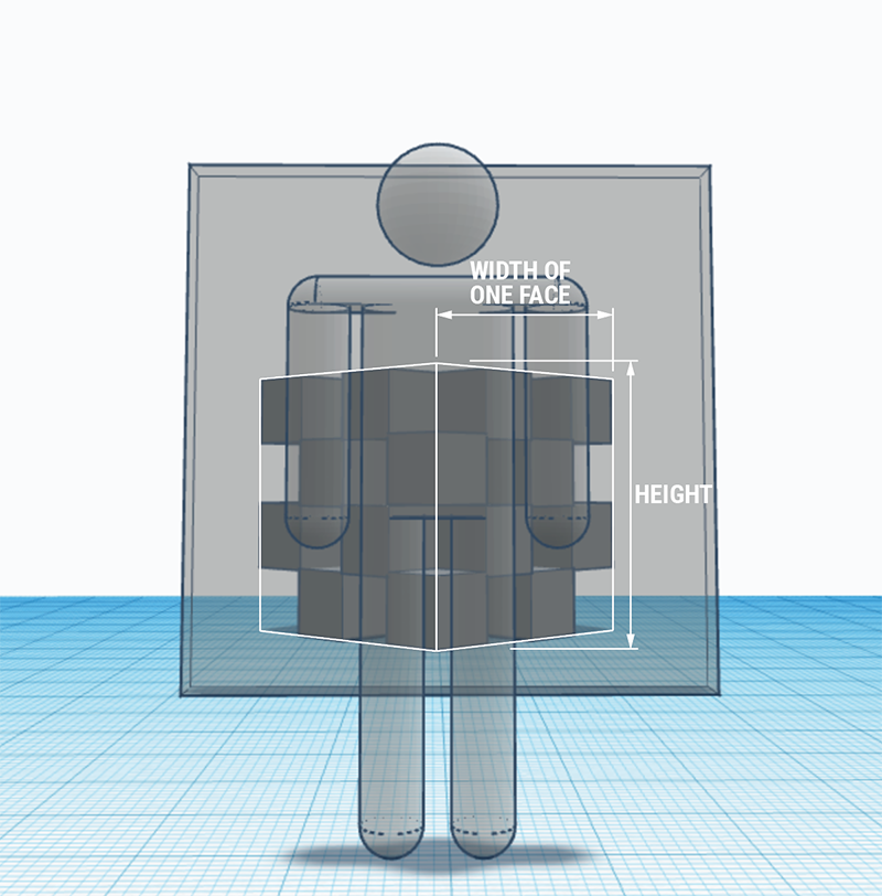
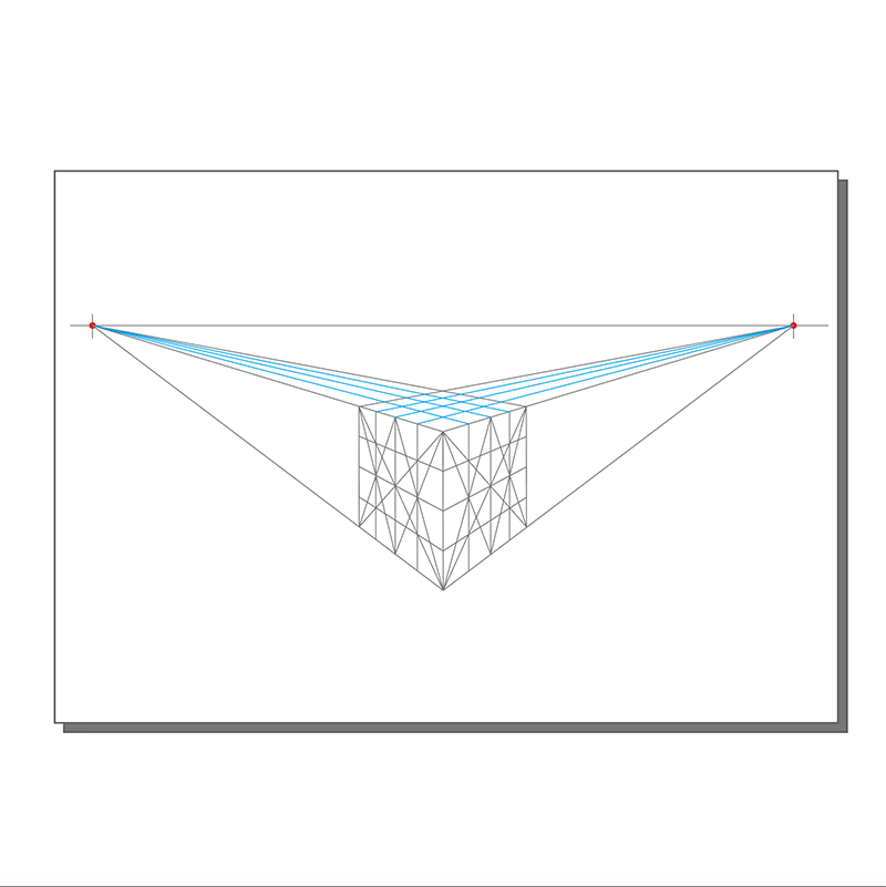
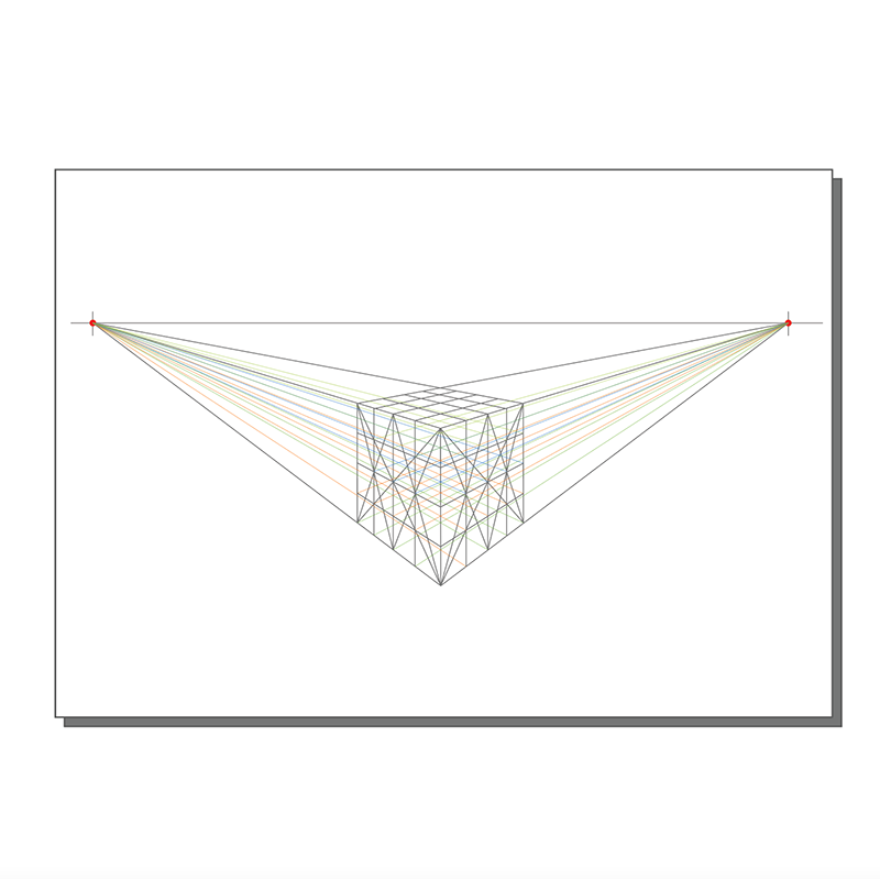
If you have been working your way through this page (and the one on One-Point Perspective) you may have seen that I make the proportions of box sides slimmer than their heights. That's right, one should. You might be asking how much thinner are they? Well there are actually methods that give mathematically accurate dimensions for objects in Two-Point Perspective. However, drawing according to precise dimensions is not required in VCD Visual Communication Design.
What is required is that students demonstrate an understanding of proportions of objects as they draw them in perspective. I have constructed the following two images to help students understand how objects become slimmer as they are rotated and viewed in Two-Point Perspective.
Jump to
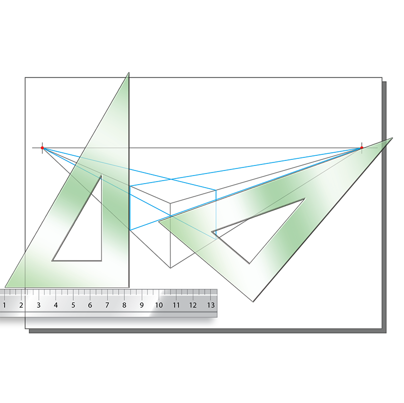
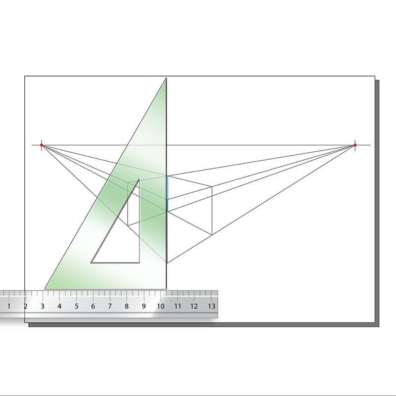
Skill 4. Measuring in 2-Point perspective
Measuring on the closest vertical
Measuring on the diagonal


task
5.1 Measuring in perspective
Jump to
Skill 5. Responding to instructions
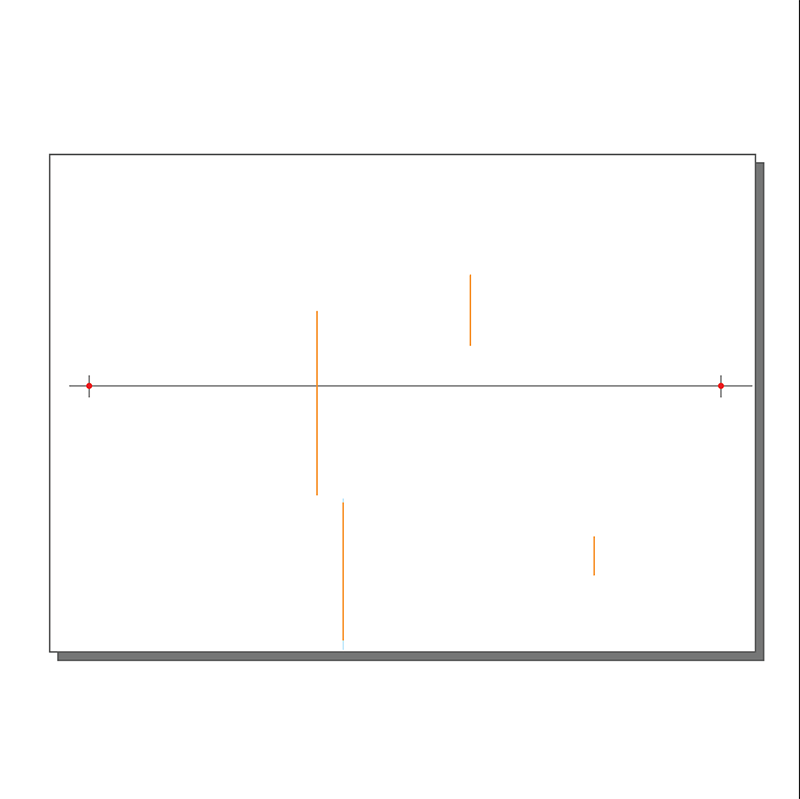
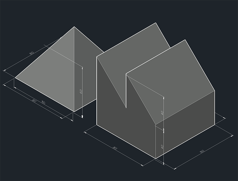
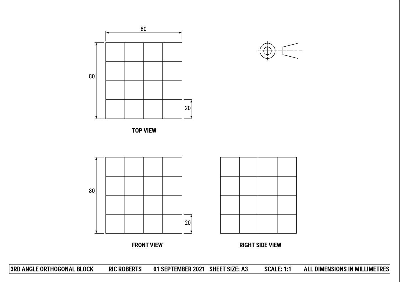
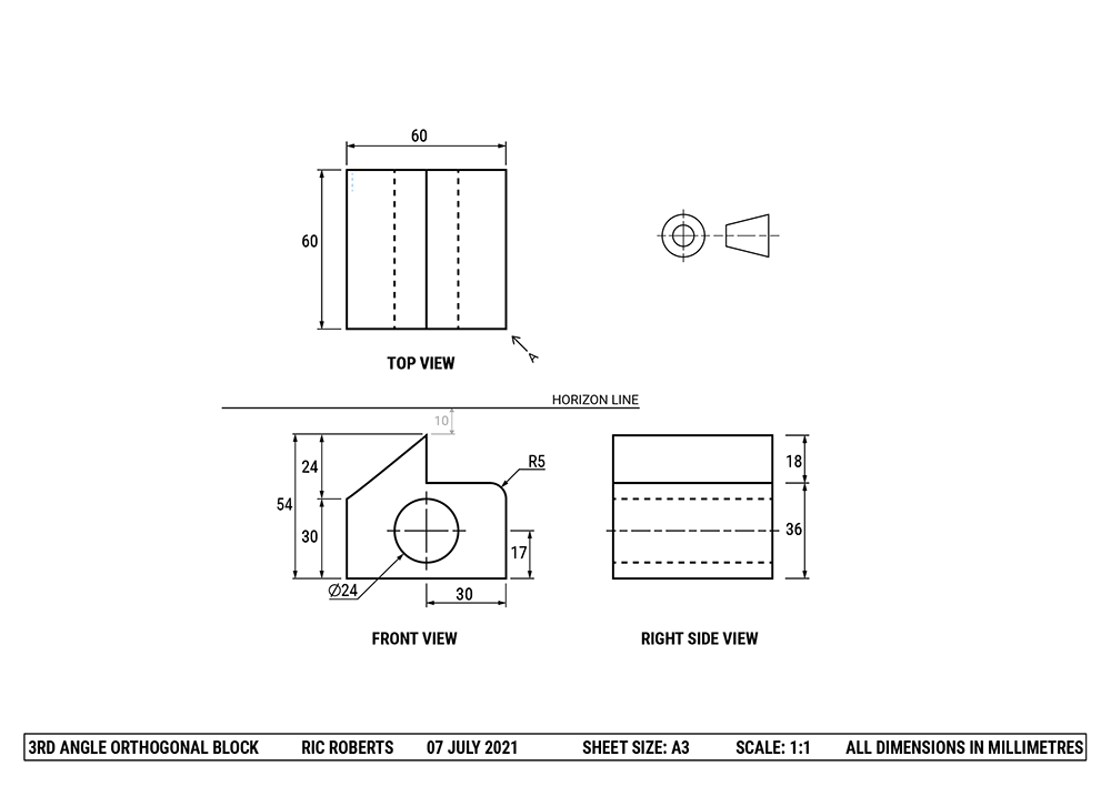
Students may have to produce a Two-Point Perspective drawing from a two-dimensional drawing such as a 3rd Angle Orthogonal. This section will explore manual ways to set up a drawing in a way that is required for tests and exams.
A sample question might read;
Draw a Two-Point Perspective of the block.
Your drawing must:
- be drawn from Point A as indicated by the arrow
- maintain similar scale and proportions
- use the Horizon Line provided in the 3rd Angle Orthogonal
- use Vanishing Points
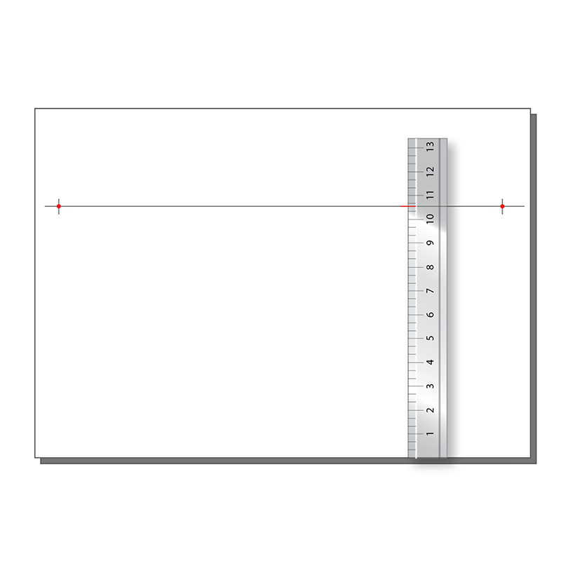
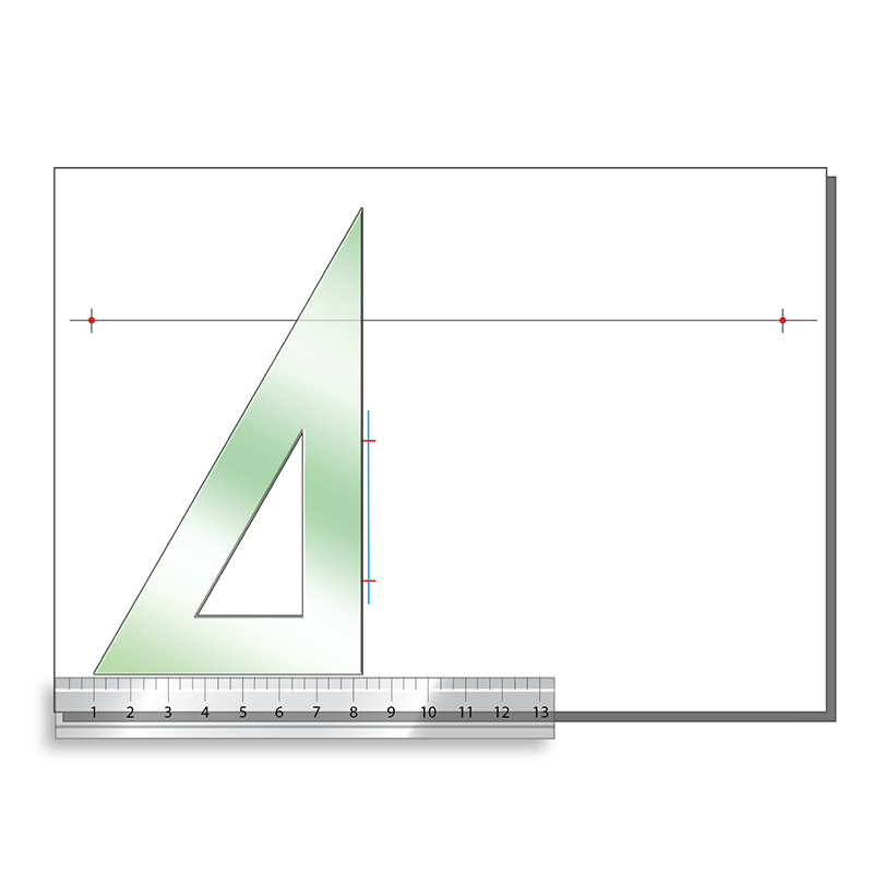
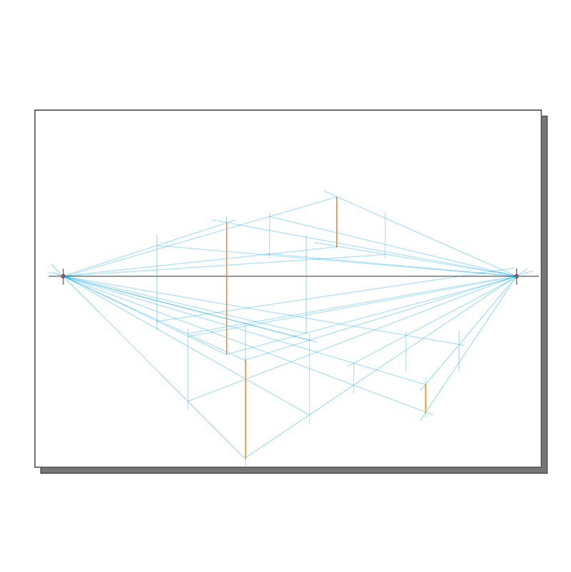
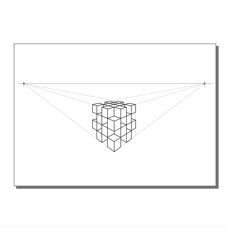
Manual Two-Point Perspective
Jump to

Ellipses in 3D Drawing
task