Third Angle
Orthogonal.
Takeaways

Good to go
Third angle orthogonal
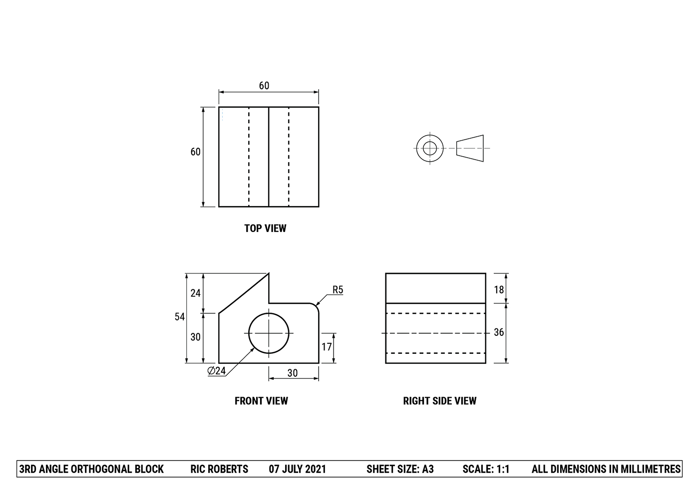
Third-angle orthogonal drawing is a method of depicting three-dimensional objects using separate two-dimensional views (top, front, and right side). It follows specific rules and conventions set by the Australian Standards Association to accurately communicate the sizes, features, and dimensions of objects for construction and manufacturing purposes.
- Proper view alignment is critical
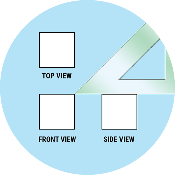
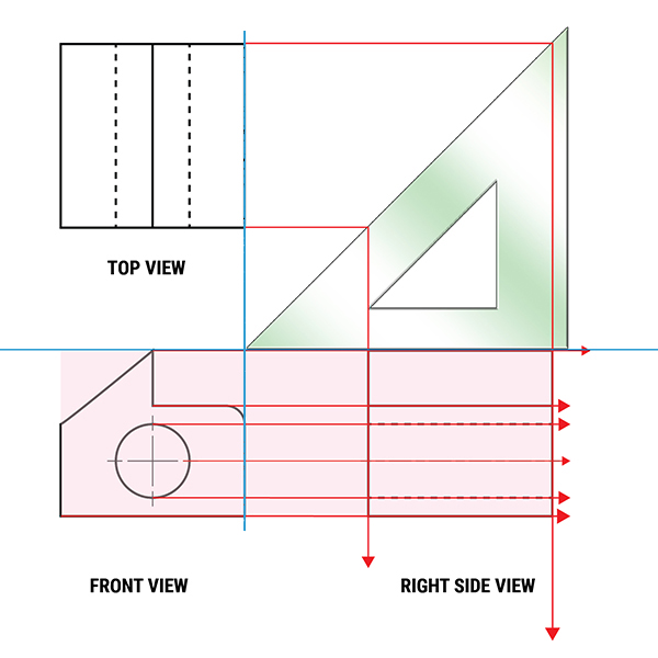
The top view must be positioned directly above the front view, and the right side view must be properly projected using a 45-degree set square. All three views must align with each other to accurately represent the object's features and dimensions. - The front view determines everything
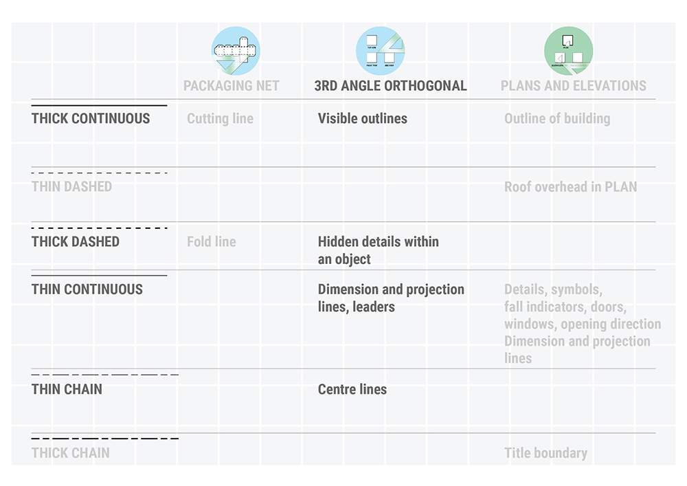
According to Australian Standards, the front view should always be the view that communicates the most information about the object. This decision affects how you orient the top view and ultimately the entire drawing layout. - Line conventions and precedence matter
Different line types (thick continuous for outlines, thick dashed for hidden details, thin chain for centres) serve specific purposes. When multiple lines occupy the same position, only the highest-precedence line is drawn. - Complete drawings require proper annotation
A finished orthogonal drawing must include view labels, accurate dimensions, the third-angle symbol, and a title block with essential information, such as scale, date, and units. These elements transform a simple drawing into a professional manufacturing document.
Model answer
Introduction
This page will teach students about making a 3rd Angle Orthogonal Drawing. We will begin with roughly sketched drawings and move to formal instrumental presentation drawings. 3rd Angle Orthogonal drawings are in Visual Communication Design are made manually and with digital-based methods using the media of vector-based and/ or CAD programs.
The purpose of 3rd angle orthogonal drawings
WHO USES THEM, WHAT ARE THEY FOR?
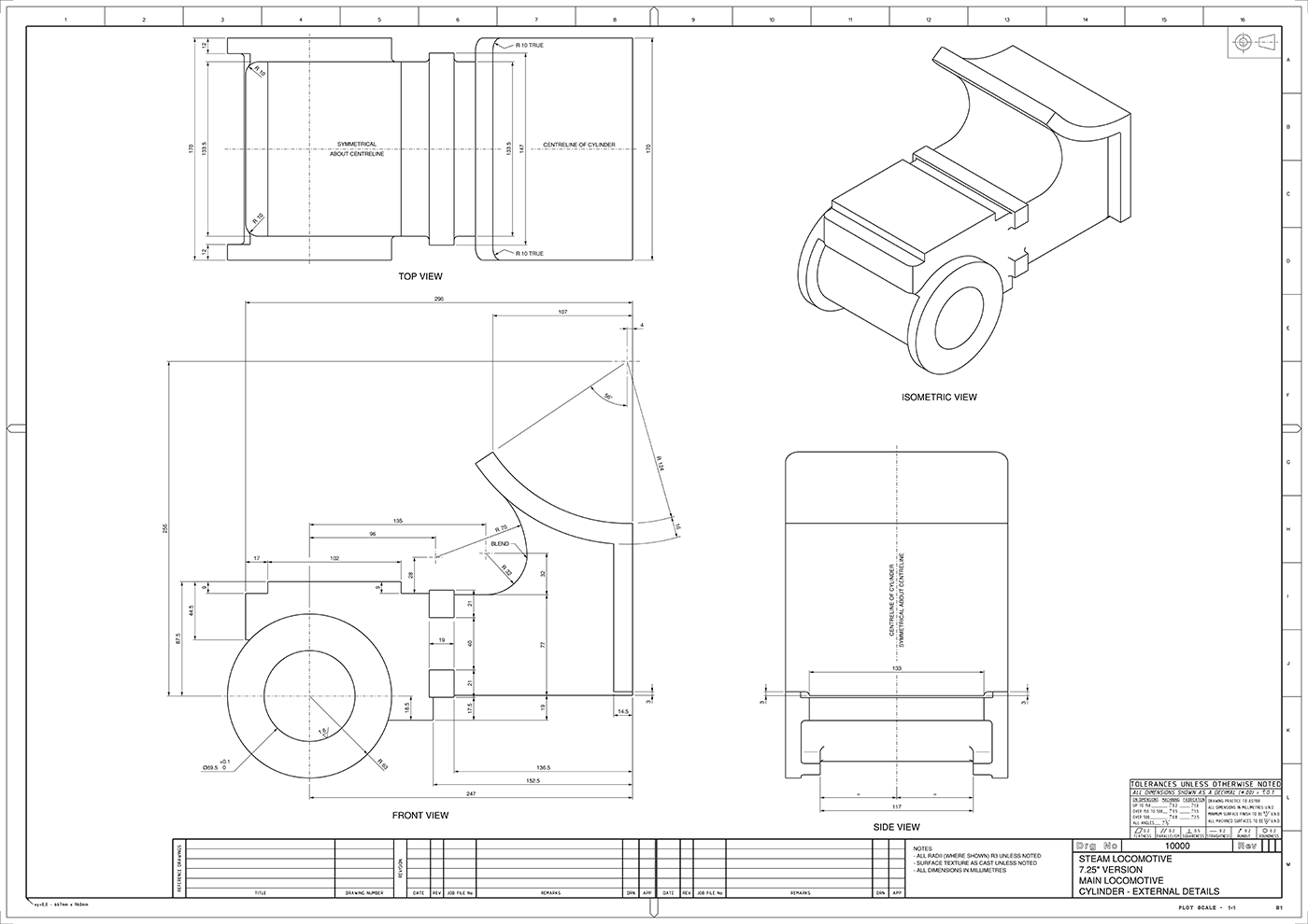
An Orthogonal drawing is a pretty serious kind of drawing. It contains information needed for making something accurately. Orthogonal drawings form part of a manufacturing contract between client and maker, so they must be drawn accurately and interpreted as the designer intended. If a product is made 'according to the drawing, the maker can be paid. If it's not, the drawing will be used to show where the product is wrong. Various kinds of 3rd Angle Orthogonal drawings are used by industrial designers, engineers, pattern makers and automotive designers.
In order for Orthogonal drawings to communicate details clearly, they need to be drawn correctly. A set of rules known as conventions has been created to ensure that 3rd Angle Orthogonal Drawings are always drawn consistently. These conventions set rules for the kinds of lines used, the ways to name things, the way to say how big things are and other details. These rules are in a document named: 'Australian Standards AS1100.'
Jump to
Making a 3rd Angle Orthogonal Drawing
What is a projection?
A three-dimensional object can be represented on a flat piece of paper by projecting the views away from the object onto transparent viewing planes. In this video, these planes are shown as pieces of glass. This set of flat planes is then folded out and becomes the paper on which the drawing is made.
A 3rd Angle Orthogonal drawing is a way to show a three-dimensional object on a flat piece of paper. As you would realise, we can't draw all the sides of an object at once unless we are Pablo Picasso!
SETTING OUT AN ORTHOGONAL DRAWING
ORIENTATION OF THE TOP VIEW
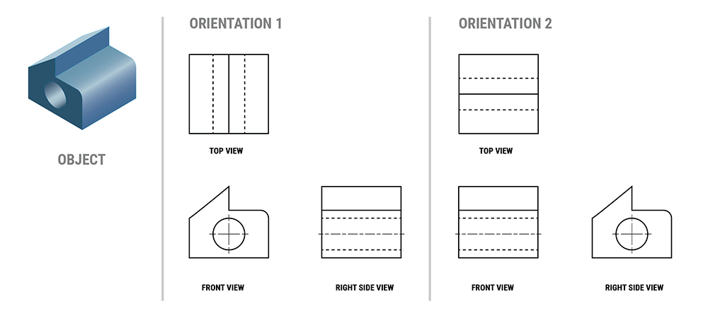
Alignment

task

1.1 Visualise 3rd angle orthogonal
1.2 sketch orthogonal
Jump to
Line conventions
Jump to
Scale
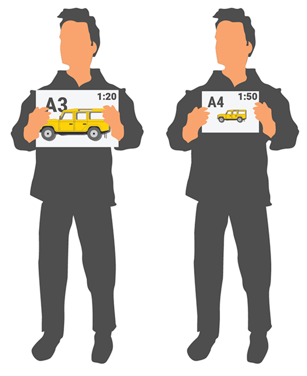
An object is seldom represented at full size in a 3rd Angle Orthogonal drawing. Students are expected to be able to select a scale for their drawings. Selecting an appropriate scale depends on the three things;
- How big is the object to be represented?
- How much of the object is to be shown/ how many views are to be shown?
- What size paper will be used.
The scale used in a drawing is nominated in the Title Block. To find out how to draw accurately in scale, explore my page on Scale, linked below.
Jump to
Scale
task
2.1 Visualise Scales
Find 5 objects around you. Find 3 with dimensions smaller than yourself and 2 with dimensions bigger than you.
Grab a ruler or tape measure and measure the height, width and depth of each object. Write these dimensions down in a table.
Convert the dimensions for each object to sizes in millimetres for each of the following scales:
- 2:1
- 1:5
- 1:10
- 1:50
- 1:100
2.2 Use scales
Jump to
Drawing a manual 3rd Angle Orthogonal
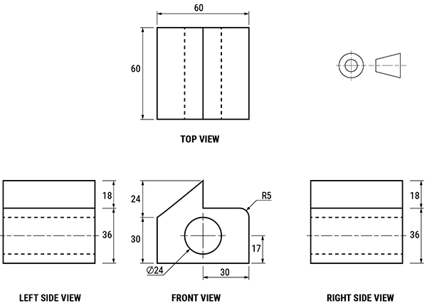
It's time to put what we know so far into practice. In this video I take students through the simple process of setting out and drawing a 3rd Angle Orthogonal Drawing based on the block seen above.
Don't forget to incorporate the line conventions found in the table above.
3rd Angle Orthogonal with manual method - part 1

task
3.1 Manual 3rd Angle Orthogonal
3.2 Manual 3rd Angle Orthogonal
Jump to
Labels and dimensions
Labels
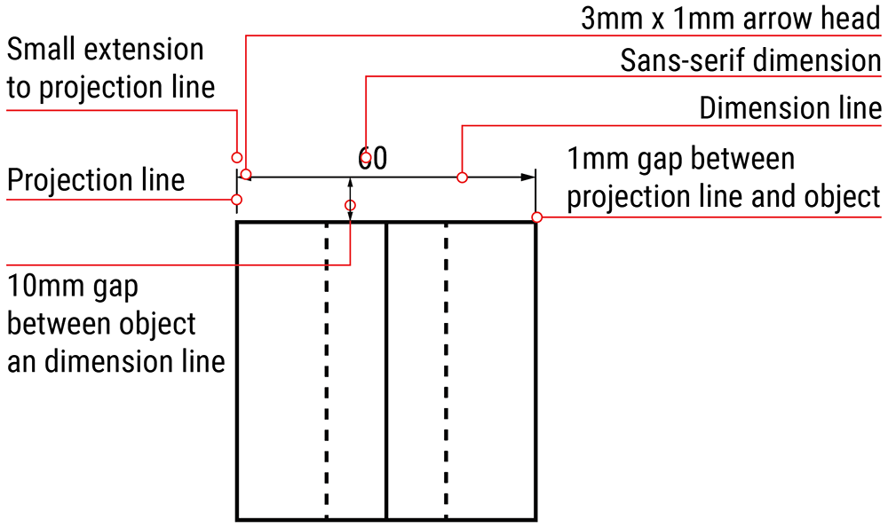
Each view in a 3rd Angle drawing must be labelled in a consistent way. The names for each view and the dimensions used to set up labels are shown here. Sans-serif capitals are used.
Jump to
Dimensions
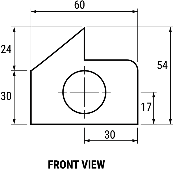
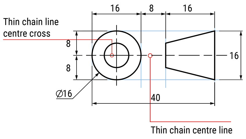
Dimensions in 3rd Angle Orthogonal drawings are annotations that indicate sizes of objects and/ or components. There are several kinds of dimensions for different parts of objects. In addition, Australian Standards shows several different acceptable ways to dimension components. This page will illustrate only one way for each dimension style.
Note: Dimension numbers identify the sizes of parts of the actual object and not the size of them as they appear in a drawing. Therefore; dimensions for the side of an object use the same number even when different views are at different scales.
Overall and intermediate Dimensions
Overall dimensions refer to the size of one complete side of an object.
Intermediate dimensions refer to the sizes of components of an object situated on one side.
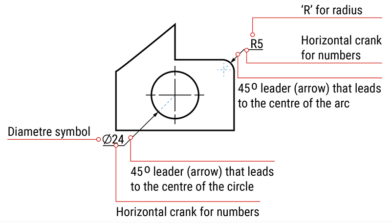
Linear dimensions
Dimensioning circles and arcs
Jump to
Symbol
Jump to
CAUTION
Lines of precedence
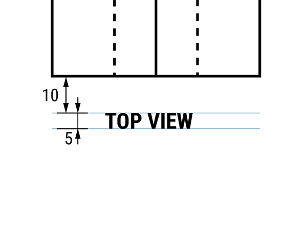
Did you know that when two kinds of lines in a 3rd Angle Orthogonal are in the same position, they are not seen together? Only one kind of line is seen at one time. This idea is known as 'lines of precedence' and means that certain kinds of lines take precedence over others. (Precedence means seen first). The order for showing lines that occur together is;
- Thick continuous (outlines)
- Thick dashed (hidden details)
- Thin chain lines (centres)
Examine the following image to see how only one line has been drawn in the middle of the TOP VIEW. Use the FRONT VIEW to help understand the form.

Jump to
Putting it together: manual and digital
3rd Angle Orthogonal with manual method - part 2
3rd Angle Orthogonal with digital method - part 1
3rd Angle Orthogonal with digital method - part 2
task
4.1 Labels
4.2 Dimensions
Make a manual 3rd Angle Orthogonal drawing of a single hole pencil sharpener. Don't forget to include hidden lines and centre lines for the hole. Dimension this drawing to show;
- overall height, width and depth
- at least one intermediate dimension
- the diametre of the outside circle
Refer to the images above for Australian Standards conventions.
4.3 Symbol
4.4 lines of precedence
Construct a FRONT and TOP VIEW of a block that has two lines that are in the same position. (Ensure that your block is a different shape from the ones shown above). Using your knowledge draw in the line that should take precedence.
For an extension activity try to create two lines in the same position on the FRONT VIEW and draw the correct line.
Jump to
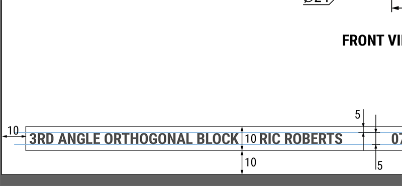
Title Block
The final part of creating your 3rd Angle Orthogonal drawing is to make your title block. The title block is usually situated at the bottom of you page and extends across from the left to right margin. It may be an enclosed or open box that is defined by lines. It should include;
- the title of the drawing
- the student name
- date drawn
- scale used
- sheet size
- reference to units used in the dimensions
task
5.1 Lego orthogonal
Use Lego or other blocks to create a complex form. Photograph it using your camera from three different angles to use as reference for your drawing.
Make a completed 3rd Angle Orthogonal using the processes described on this page. Don't forget to follow the steps for selecting an appropriate scale, add labels, dimensions, symbol and title block in accordance with Australian Standards and VCAA Technical Drawing Specifications.
Use a manual or digital method as directed by your teacher.